Details
- Program: Adobe Illustrator CS3 – CS5
- Difficulty: Intermediate
- Estimated Completion Time: 2 hours
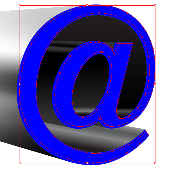
Final Product What You'll Be Creating
This work is a common project together with
Iaroslav Lazunov and
Oleksandr Iegupov.
This tutorial is for intermediate Illustrator users. We’ll use
3D-modeling, gradients, blending modes, blends, gradient meshes for
creating the picture. Let’s get started!
Step 1
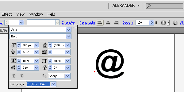
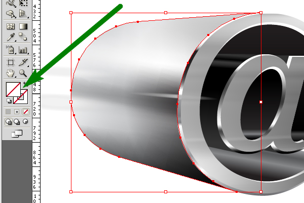
Take the Type Tool (T), click on the Character Panel, set the Font
Family to Arial and the Font Style to Bold, and create the e-mail sign.
Then go to Type > Create Outlines (Command + Shift + O), take the
Pen Tool (P), delete the superstitious anchor points, and convert the
e-mail sign to the following path by using the Direct Selection Tool
(A). See the diagram where the green transparent path is the original
e-mail sign, and the gray selected path is what you need to have after
converting.
Step 2
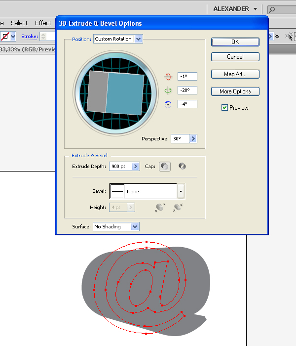
Now go to Effect > 3D > Extrude & Bevel and set there the following values that you can see on the diagram below.
Pay attention to the angle of the Perspective and the Rendering
Style that is set to “No shading.” This rendering style is needed for
decreasing the quantity of the surfaces after expanding 3D object.
Step 3
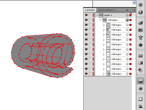
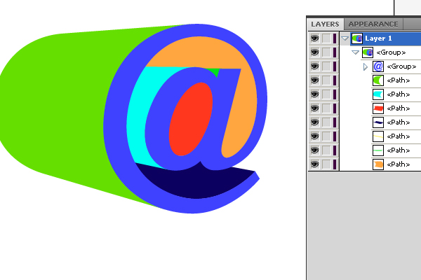
Go to Object > Expand Appearance and then go to Object > Ungroup.
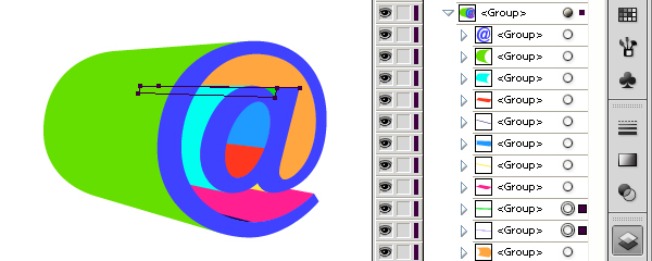
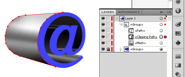
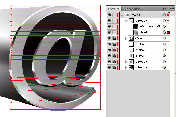
Now recolor all the parts of the 3D object in order to make them more visible. See the Layers palette below.
Step 4
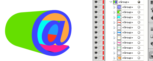
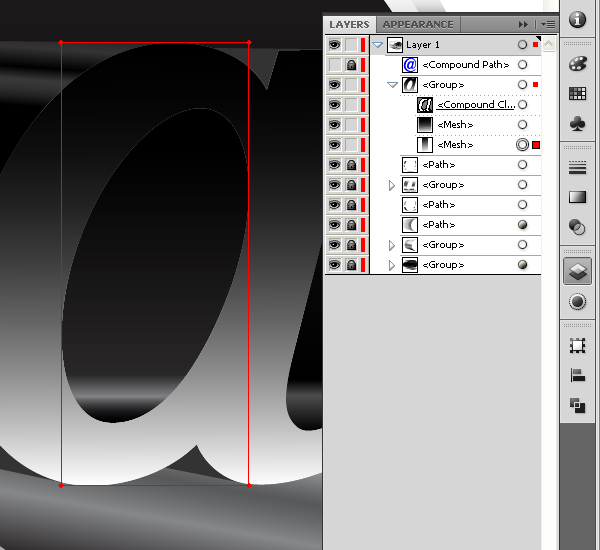
Take the Selection Tool (V) and select the following groups as shown.
Then go to Pathfinder palette and click on the Unite button. And you will receive one path from two groups.
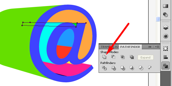
Step 5
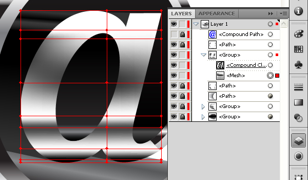
Also unite the following groups in pairs.
After that you must have 7 paths and 1 group. See the layers palette as shown.
Step 6
Select the path which is shown in the figure below and fill it with
the linear gradient of gray and black in colors. Pay attention to the
light spot in the bottom of the 3D object.
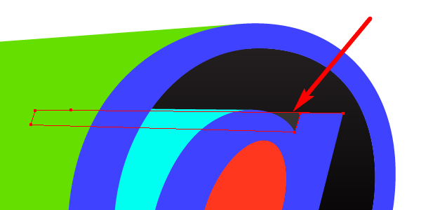
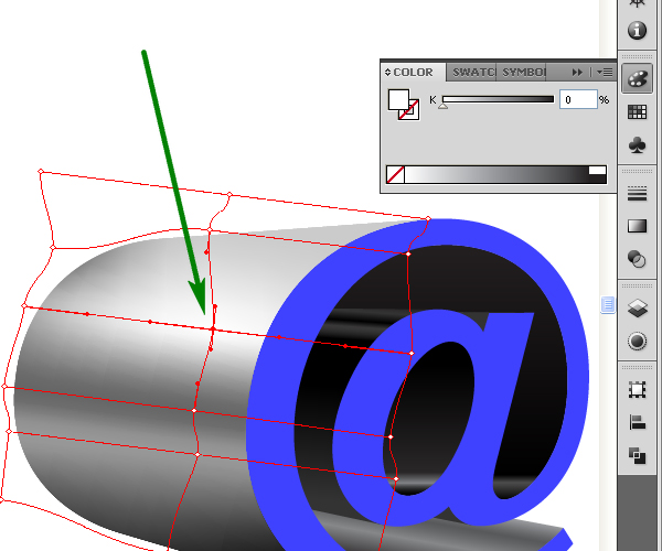
Select the next path and fill it with a dark gray color. Almost all
the path is invisible. The visible part of it is shown with an arrow in
the figure below.
Select the following path and fill it with the linear gradient.
Now select the next path and fill it with a dark gray color. The
color of the filling must coincide with the corresponding color of the
path’s part, which has just been filled with the gradient.
Fill the next path with the a linear gradient. Pay attention to the light spot.
Select the following path and fill it with the a linear gradient.
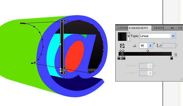
Step 7
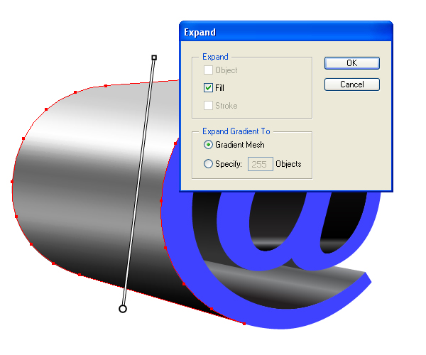
Select the lateral surface of 3D object and fill it with the angled linear gradient.
Now go to Object > Expand and expand this gradient filling to the gradient mesh. See the diagram below for reference.
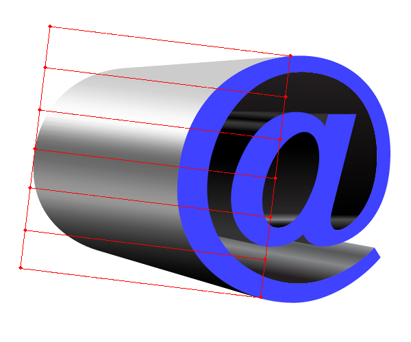
Now go to Object > Ungroup. And you will receive the group of
Mesh and Clipping paths that limits the Mesh to the bounds of the
lateral surface of the 3D object.
Step 8
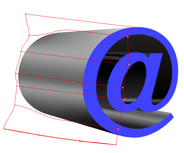
Take the Mesh Tool (U) and select and drag the mesh anchor points in
order to convert the mesh gradient filling to the analogue of the
conical gradient filling. One way of creating this is decreasing the
space between the left anchor points of the mesh.
Click in the center of the mesh with the Mesh Tool (U) selected. You
will then have a new mesh line. Now create a light spot by selecting
the central anchor point (shown by an arrow in the diagram) and set the
white color for it.
Step 9
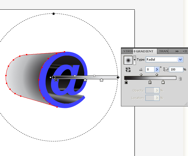
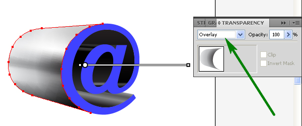
Select the Clipping path in the Mesh group and the Clipping path, copy it and paste in front (Command + C then Command + F).
Fill this path with a Radial gradient filling.
Now go to the Transparency palette and set there the Blending mode to Overlay.
Step 10
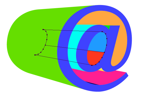
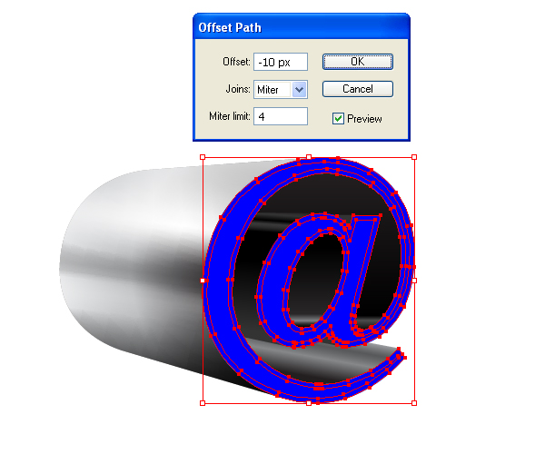
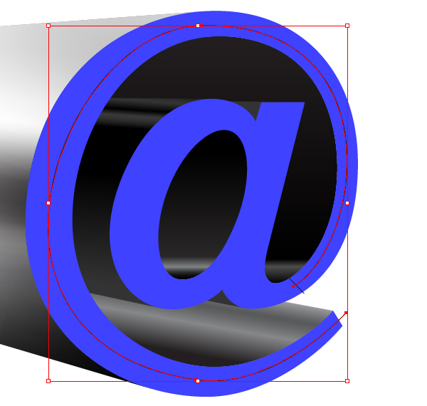
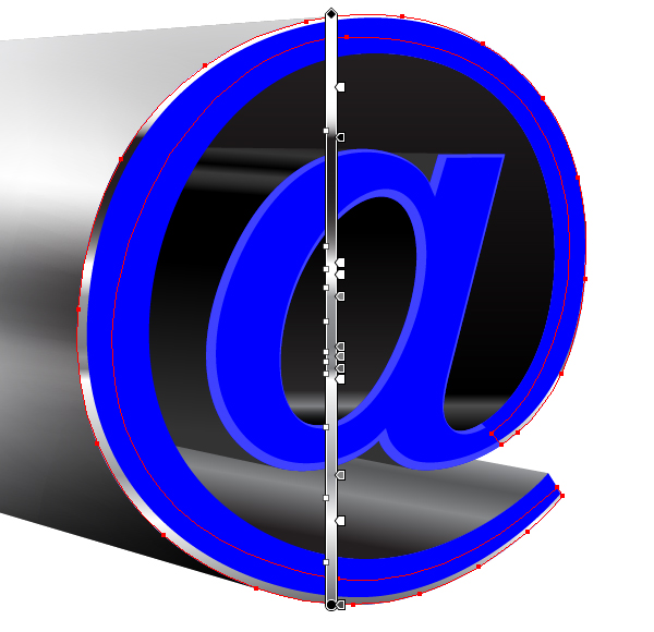
Select the blue sign “@” with the Selection Tool (V). Copy it and
paste it in front (Command + C then Command + F). Now go to Object >
Path > Offset Path. Set in the dialogue box the following values for
items which are shown on the figure below.
Move the offset path in order to create analogues of bevels of the 3D object.
Step 11
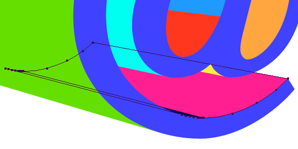
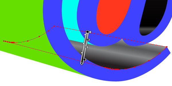
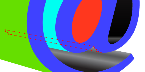
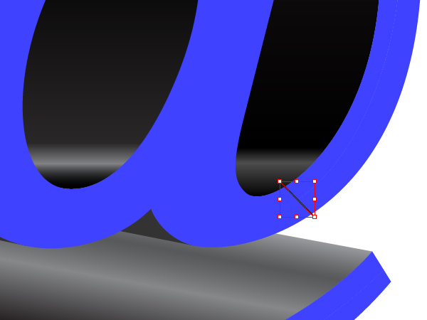
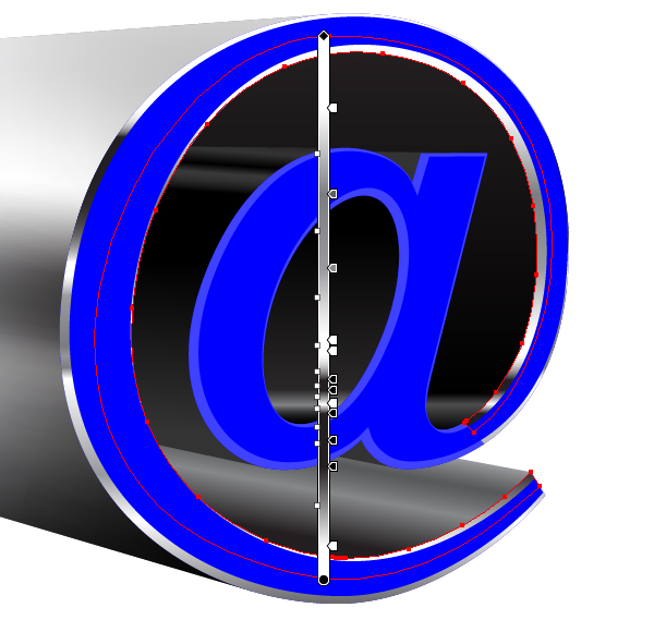
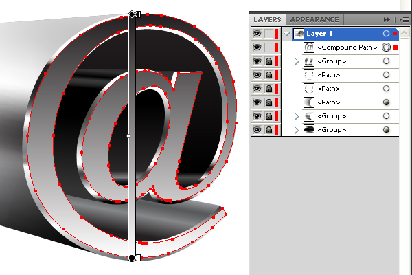
Take the Line Segment Tool (\) and create the line, which is shown
in the figure below (offset path that has just been created is
invisible on the diagram and lying on the blue visible path). This line
must intersect the blue sign “@”.
Now take the Pen Tool (P) and create a spiral line that is lying in the middle of the blue sign “@”.
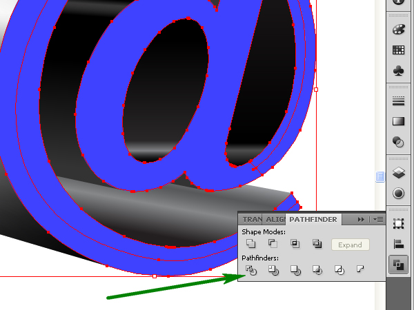
Select these lines with the Selection Tool (V) and set the Stroke of them to None. Now select these lines and the sign “@” itself and go to the Pathfinder palette. Click there on the Divide button. And you will have three different paths after that.
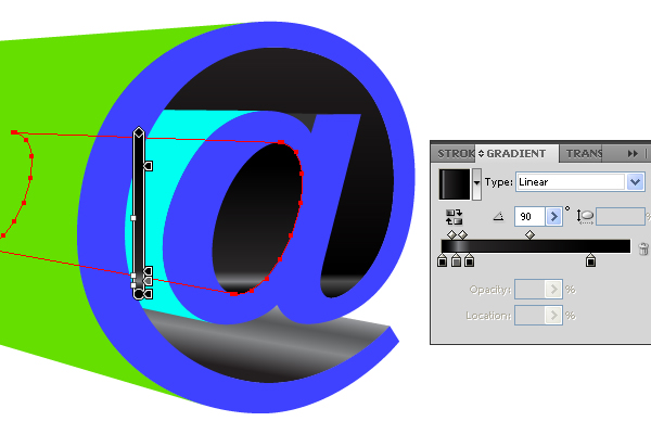
Step 12
Select the following path that represents a bevel and fill it with the linear vertical gradient filling.
Select the next path that represents another bevel and fill it with the linear vertical gradient filling too.
Step 13
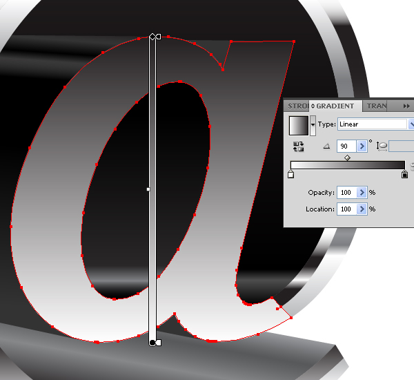
Select the letter “a” and fill it with the linear vertical gradient.
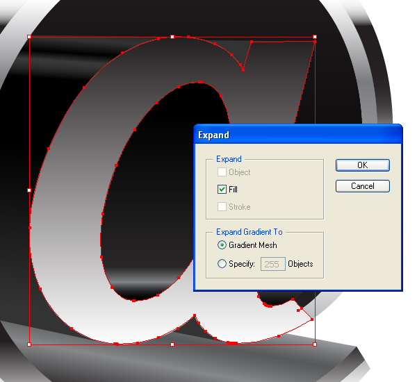
Now go to Object > Expand and expand this gradient to gradient mesh. Then go to Object > Ungroup. This command allows you to convert a gradient into the mesh, which will have anchor points of the same color as the gradient stops had.
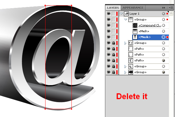
Go to the Layers palette and delete the inner mesh from the gradient mesh group.
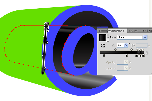
Step 14
Select the outer mesh in the gradient mesh group in the Layers palette, take the Mesh Tool (U) and click on the borders of the gradient mesh in order to add anchor points and mesh lines. Then select the mesh anchor points with the Mesh Tool (U) and set colors to them as you want. You must receive the following picture of lights and shadow.
Step 15
Select the top blue compound path and fill it with the vertical gradient.
Now go to Object > Expand and expand this gradient to gradient mesh. Then go to Object > Ungroup. Go to the Layers palette and delete the inner mesh from the gradient mesh group.
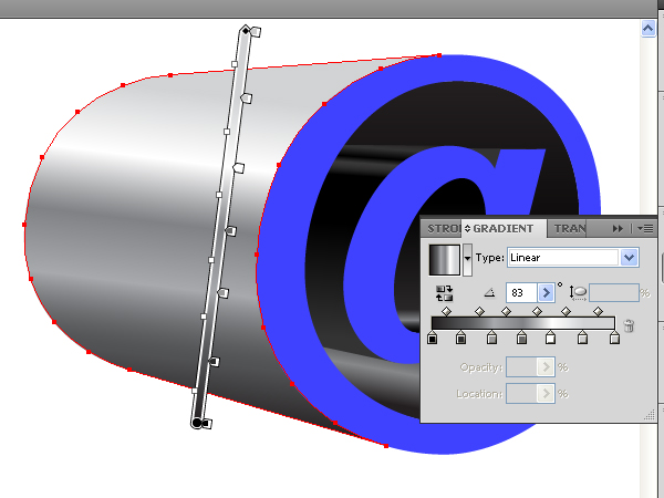
Step 16
Select the outer mesh in the gradient mesh group in the Layers palette, take the Mesh Tool (U) and add anchor points and mesh lines. Recolor and move it in order to receive the following picture.
Step 17
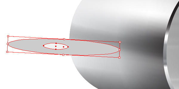
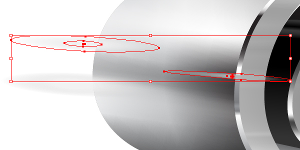
Take the Ellipse Tool (L), draw two ellipses over the back of the lateral surface of the 3D object and go to Object > Transform > Rotate in order to bend these ellipses.
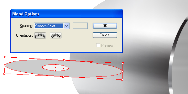
Go to Object > Blend > Blend options, and set the Spacing value to Smooth color.
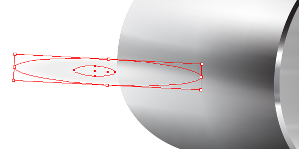
Set the Opacity for the biggest ellipse to 0. Then go to Object > Blend > Make (Command + Alt + B).
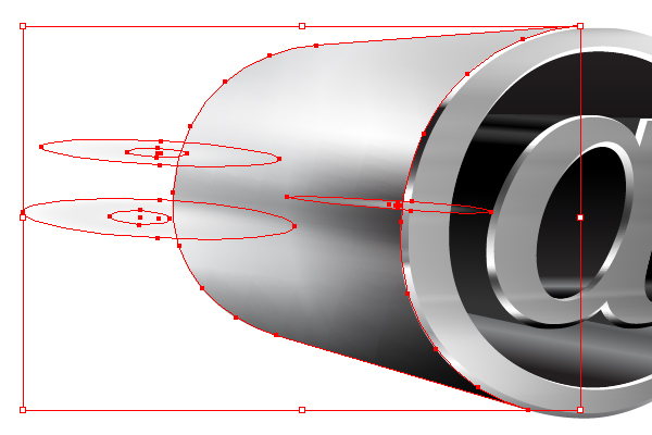
Step 18
Create two other blends on the lateral surface that you can see in the picture below.
Select the lateral surface, copy it and paste in front (Command + C then Command + F). Set for this path both: the Stroke and the Fill color to None.
Now select simultaneously all three blends and this path with the help of the Selection Tool (V).
And go to Object > Clipping Mask > Make (Command + 7).
Step 19
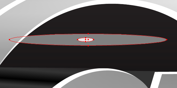
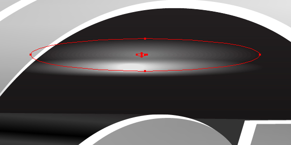
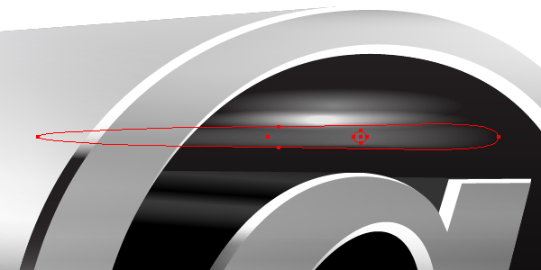
Take the Ellipse Tool (L) and create two ellipses in the inner part of the 3D object above the letter “a”.
Set the Opacity of the biggest ellipse to 0.
Now go to Object > Blend > Make (Command + Alt + B).
Step 20
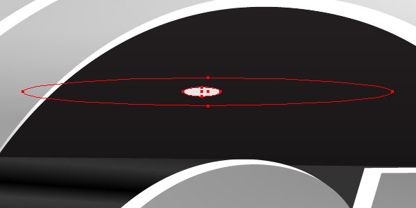
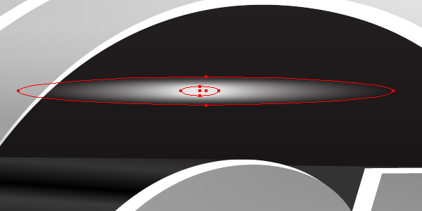
Create the next blend above this one.
And then create the third blend under the first one.
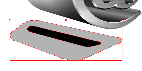
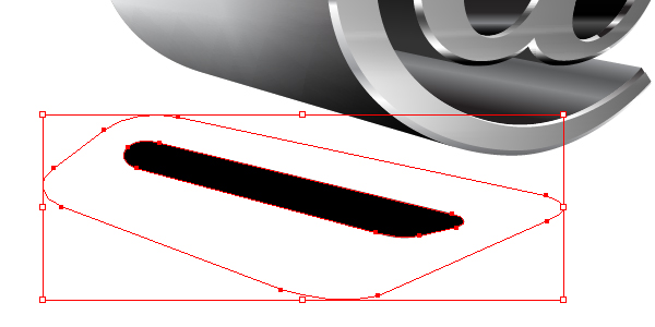
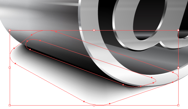
Step 21
Let’s create a shadow from the 3D object now. Take the Pen Tool (P) and draw the following two paths.
Set the Opacity for the biggest path to 0.
Now go to Object > Blend > Make and move the shadow under the 3D object. Scale it there in order to represent beauty.
Conclusion
So, you have just made a 3D @-sign. I hope you enjoyed this tutorial and smoothly completed all parts.


No comments:
Post a Comment